FEVF-89TX-1
Types Illustration FEVF
POWER SOURCE Voltage
| 3 |
| Phase of Power |
| 1 : 1-Phase |
| 3 : 3-Phase |
| 2 |
| Input Voltage |
| 1:110V(AC) |
| 2:220V(AC) |
| 3:380V(AC) |
| 4:400V(AC) |
| 5:415V(AC) |
| 6:440V(AC) |
| 7:460V(AC) |
Motor Specification
| 2 |
| 1 : 1-Phase 220V |
| 3 : 3-Phase 380V |
| 4 : 3-Phase 440V |
| P5-05 |
| P5:1/2HP |
| 01:1HP |
| 02:2HP |
| 03:3HP |
| 05:5HP |
| 07:7.5HP |
| 10:10HP |
| : : |
| 60:60HP |
| TYPE | 322P5 | 32201 | 32202 | 32203 | 32205 | 32207 | 32210 | 32215 | 32220 | 32203 | 32203 | 32240 | 32250 | 32260 |
Motor Output |
0.4 | 0.75 | 1.5 | 2.2 | 3.7 | 5.5 | 7.5 | 11 | 15 | 18.5 | 22 | 30 | 37 | 45 |
Motor Hp |
1/2 | 1 | 2 | 3 | 5 | 7.5 | 10 | 15 | 20 | 25 | 30 | 40 | 50 | 60 |
Rated output current |
3.1 | 4.5 | 7 | 10.5 | 16 | 24 | 32 | 45 | 60 | 72 | 85 | 110 | 140 | 170 |
Inverter Capacity |
1.2 | 1.4 | 2.7 | 4 | 6 | 10 | 13.7 | 17.9 | 22 | 27.5 | 33 | 43 | 52 | 65 |
Line Souce |
3-Phase 220~230v±10% 50/60HZ±5% | |||||||||||||
Max output Voltage |
3-Phase 0~230v Three phase 0-230V | |||||||||||||
| TYPE | 333P5 344P5 |
33301 34401 |
33302 34402 |
33303 34403 |
33305 34405 |
33307 34407 |
33310 34410 |
33315 34415 |
33320 34420 |
33325 34425 |
33330 34430 |
33340 34440 |
33350 34450 |
33360 34460 |
Motor Output |
0.4 | 0.75 | 1.5 | 2.2 | 3.7 | 5.5 | 7.5 | 11 | 15 | 18.5 | 22 | 30 | 37 | 45 |
Motor Hp |
1/2 | 1 | 2 | 3 | 5 | 7.5 | 10 | 15 | 20 | 25 | 30 | 40 | 50 | 60 |
Rated output current |
1.5 | 2.3 | 3.8 | 5.2 | 8.8 | 12 | 16 | 24 | 30 | 39 | 45 | 60 | 73 | 85 |
Inverter Capacity |
1 | 1.7 | 2.9 | 4 | 6.7 | 10.3 | 12.3 | 17.9 | 22 | 28 | 34 | 44 | 53 | 65 |
Line Souce |
3-Phase 380~440v±10% 50/60HZ±5% | |||||||||||||
Max output Voltage |
3-Phase 0~230v Three phase 0-380V 0-460V | |||||||||||||
Control Method |
Sine Wave Pwm (V/F contorol) | |||||||||||||
Torque Signal(MAN) |
Manual Dc 0-10V Aut Dc 0-10V or 0~20mA | |||||||||||||
Accel/Decel Time |
1~11sec, for torque priority, acceleration or deceleration will harmonize without limited by ACCEL/DECEL. | |||||||||||||
Braking Torque |
Lower then 20% (with optional braking resistor)be related to Torque magnitude when torque control. | |||||||||||||
Overload Capacity |
150% Rated output current resistor | |||||||||||||
Over Voltage |
DC Voltage >410V(Power supply110/220V AC) DC Voltage >810V(Power supply380/440V AC) DC Bus voltage exceed | |||||||||||||
Operation Temperature |
-10~40℃/0~90℃ Relative humidity not dewing | |||||||||||||
Vibration-Proof |
1G(9.8m/s2) or less | |||||||||||||
| Terminal Types | Terminal Symbol | Terminal | Description | |
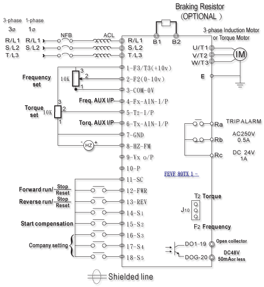
Main Circuits Terminal |
Power | R/L1.S/L2.T/L3 | AC power input terminal | Three phase power source input. Please connect R/L1.S/L2 terminal if it is single phase power. |
| Motor | U/T1.V/T2.W/T3 | Motor wires terminal | Three phase variable frequency, voltage, current connect to motor wires. | |
Brake unit |
B1 . B2 | Braking resistor terminal | External braking resistor. | |
| P . N | External braking module | External braking module terminal. | ||
| Ground | Ground terminal | The third kind 100Ω or less (200v class), 10Ω or less(400v class) | ||
Control Circuit Terminal |
Frequency instruction input terminal |
1-F3/T3(+10v) 2-F2/(0~10v) 3-GND |
1-F3/T3:Frequency and Torque source. 2-F2:Input terminal. |
 Terminal1.2.3. and J1 socket. Only one selected. |
| 4-Fx | Frequency instruction auxiliary input terminal. | For external frequency signal input terminal(0~10v) | ||
Torque instruction input terminal |
1-F3/T3(+10v) 5-T2/(0~10v) 7-GND |
Torque instruction source and input terminal. |  Terminal 5 and J2 socket . Only one selected. |
|
| 6-Tx | Torque auxiliary input terminal. | For external torque signal input terminal(0~10v) | ||
Forward Run Revers |
12-FWR 13-REV 11-SC |
 |
11-SC and 12-FWR Close→Forward Run, open→ stop/Reset, 11-SC and 13-REV close→Reverse Run, open→stop/Reset | |
Start Torque compensation |
||||
| Frequency Meter | 7-GND 8-Hz-FM |
External Frequency DC0~10v。 | ||
10-P |
10-P +15v | Voltage +15v 20mA or less | Operating panel, digital meter power +15V, 20mA or less. | |
| Torque / Frequency voltage output | 9-Vx (0~10v) 4-Fx 6-Tx |
Auto increment / decrement for Torque / Frequency |  (optional) (optional) |
|
Torque / Frequency increment or decrement |
 |
Open:increment Close:decrement |
Increment +v Decrement -v (optional) |
|
 |
Open:increment Close:decrement |
Increment +T Decrement -T (optional) |
||
 |
Torque / Frequency increment or decrement reset Terminal | Close: For frequency / torque increment decrement reset and return to initial torque or frequency.(optional) | ||
TRIP ALARM |
Rc Rb Ra |
TRIP ALARM terminal |
  TRIP Relay contact TRIP Relay contact |
|
19-D01 20-DOG |
 DC48v 50mA or less DC48v 50mA or less |
|||
Inverter abnormal trip reset |
 |
 |
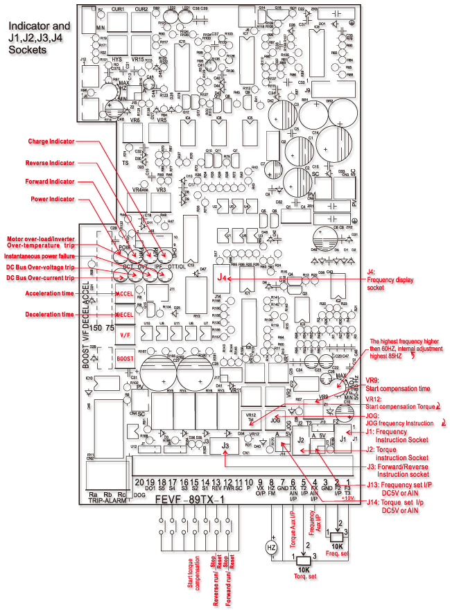
Inverter abnormal trip OCT(over current) OVT(over voltage) IPF(Instantaneous power failure) OTT/OC(Inverter over temperature or motor overload) When abnormal trip, red indicator lights, After breakdown terminate, only need to turn on, stop and reset again, then abnormal trip red indicator eliminates, and the inverter could be uccessfully operated. | |
台灣省台中市西屯區寶慶街18巷2號
TEL:886-4-27018533.886-4-27052660
FAX:886-4-27084920
No.2, Ln. 18, Baoqing St., Xitun Dist., Taichung City 407, Taiwan (R.O.C.)
E-mail:fumore1689@gmail.com